Creating a Procedural Cog in Blender Using Geometry Nodes

Today I experimented with creating a cog with Blender using Geometry Nodes. The goal was to generate a parametric cog that can be animated smoothly, with all teeth and base geometry controlled procedurally. This approach makes it easy to tweak the number of teeth, the tooth spacing, and rotation speed without manually editing the mesh.
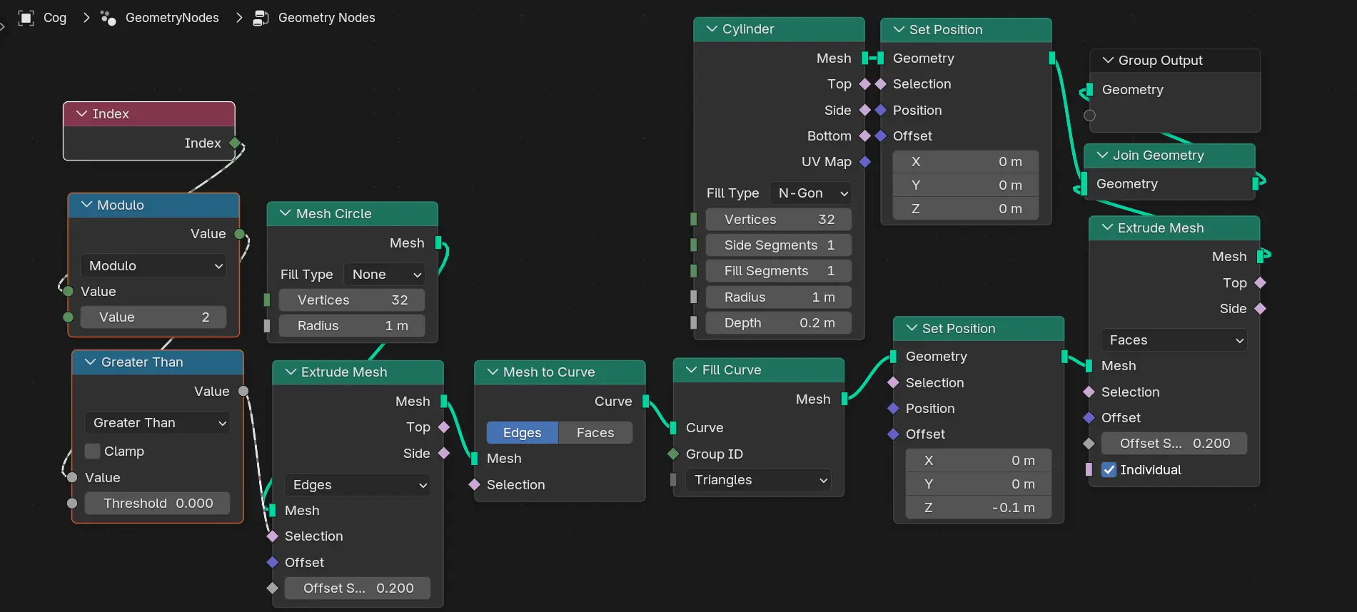
Steps taken:
-
Start with a base circle
Add a Mesh Circle node in Geometry Nodes. Define the number of vertices to match the total positions for teeth + gaps. -
Select vertices for teeth
Use the Index node and modulo math to select every other vertex. Convert the selection into a mask to identify which vertices will become teeth. -
Extrude teeth outward
Use Extrude Mesh → Offset Along Normals to pull the selected vertices outward, forming the cog teeth. Adjust extrusion distance for desired tooth height. -
Add the base cylinder
Create a Cylinder primitive node for the cog base. Translate it along Z to sit correctly under the teeth. Join Geometry to combine the cylinder and teeth. -
Fill top and bottom faces of teeth
Convert the teeth edges to curves, use a Fill Curve node, and then extrude along Z to close the tops.
This setup allows fully procedural cogs with adjustable parameters, making it easy to experiment with different designs. It’s a neat example of how Geometry Nodes can handle complex procedural geometry entirely inside Blender.
Here’s how it looks: